
Adsorptive processes
In these processes, the substances that are to be removed from the wastewater are deposited on the surface of a solid (adsorbent). In this context, activated carbon is used as an adsorbent. In comparison to other adsorbent materials, activated carbon is more cost-effective and able to adsorb a wide spectrum of materials. However, it has a specific adsorption capacity and has to be replaced if the capacity is exhausted.
In municipal wastewater treatment, both powder and granular activated carbon can be used for the removal of micropollutants. The type of activated carbon defines which technical process design is used for adsorptive wastewater treatment. Different process variants have already been investigated for both powder and granular activated carbon.
-
> Powder activated carbon (PAC)
Powder activated carbon (PAC) is ground charcoal. According to DIN 12903, at least 95 per cent of the mass fraction must have a grain size of less than 150 µm and correspond to the particle size distribution specified by the manufacturer in order for charcoal to be qualified as PAC. Commercial powder activated carbon products typically show an average particle size of 10 µm to 50 µm.
In wastewater treatment, the PAC is directly added to the wastewater to be treated. The adsorption process takes place as long as the PAC is in contact with the wastewater. For this purpose, the coal is to be mixed with a sufficient amount of wastewater. Since, only significantly shorter contact periods can be achieved than required to reach the adsorption equilibrium for technical reasons, the PAC is enriched during the treatment process in order to enhance use of its adsorption capacity in municipal wastewater treatment. After a sufficient contact period, the PAC has to be extracted from the wastewater.
Powder activated carbon can be added at different points in the wastewater treatment plant in order to remova micropollutants. Using biological treatment as a reference point, the adsorptive treatment can be carried out simultaneously or succeed the biological treatment. In the case of downstream treatment, the partially loaded PAC can also be diverted from the subsequent treatment process and returned to the biological stage for repeated loading in accordance with the countercurrent principle. Various options are available for the design of the downstream PAC introduction. Until today, the two options of dosing the PAC in a separate adsorption stage or directly before the wastewater enters a filter have been investigated. The two process variants differ in the contact period and the retention time of the PAC in the adsorptive stage on the one hand and in the manner of adsorbent guidance with regard to multiple loading on the other hand.
PAC dosing in a separate adsorption stage (see Figure 1) has already been implemented on a large scale in several wastewater treatment plants in Baden-Wurttemberg. The adsorption stage consists of a contact reactor and a sedimentation tank. The PAC is initially added to the biologically treated wastewater of the contact reactor. In the subsequent sedimentation tank, the PAC is separated from the wastewater by adding metal salts and polymers. The deposed ‘carbon sludge’ is returned to the contact reactor for reuse as ‘recirculation carbon’ to enhance utilisation of the activated carbon. This way, the retention time of the PAC in the system is decoupled from the retention time of the wastewater. The excess carbon is returned to the biological stage in accordance with the countercurrent principle in order to use the remaining adsorption capacity of the activated carbon. A filter that is positioned after the sedimentation tank separates the non-sedimented PAC from the treated wastewater.
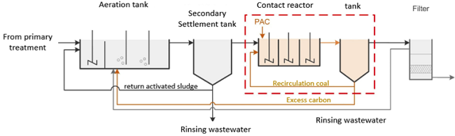
Figure 1: Schematic diagram of a separate adsorption stage for the elimination of micropollutants
Another process variant is PAC dosing before filtration (see Figure 2). The reserve space of a sand filter can also be used as space where the activated carbon comes into contact with the wastewater. The PAC is separated in the following filter bed. The deposit of the PAC in the filter bed allows for further adsorption of the wastewater constituents. By returning the rinsing wastewater to the biological stage, the retention time of the PAC in the treatment system can be maximised in order to achieve an efficient use of the PAC.
The advantage of this process variant is the streamlined integration of the adsorptive treatment unit into plants with an existing filter system.
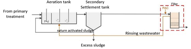
Figure 2: Process diagram for direct PAC dosing before filtration
In the simultaneous process variant, the PAC is added directly to the aeration tank (see Figure 3). The aeration tank also serves as a contact area for adsorptive treatment. The PAC is incorporated into the activated sludge and removed from the treatment stage together with the excess sludge. If the PAC is insufficiently retained in the secondary settlement tank, it is necessary to integrate a filter downstream.
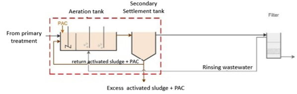
Figure 3: Process diagram of simultaneous introduction of PAC
-
> Granulated activated Carbon (GAC)
The typical grain size of granulated activated carbon ranges between 0.5 mm to 4 mm. Granular activated carbon is used in fixed-bed adsorbers. In this context, the wastewater flows through the GAC bed and any micropollutants are adsorbed on the activated carbon. An additional separator that succeeds the grain carbon filter is not required. If the adsorption capacity has been fully utilised, the activated carbon is removed. It can then be reactivated and reused for adsorption.
Granulated activated carbon is used after the biological treatment. In this case, two variants of using GAC are available. With the first variant, an existing sand filter is converted into an activated carbon filter (see Figure 4). For this purpose, the existing filter material is replaced with granulated activated carbon. In wastewater treatment plants with no or limited space for expansion, this variant constitutes an option of eliminating micropollutants. In addition to micropollutants, the granulated carbon filter also retains solid matter. However, the retention of solids in the filter bed results in increased pressure loss, thus rendering the installation of a backwashing system necessary. The rinsing wastewater can be discharged into the biological stage.
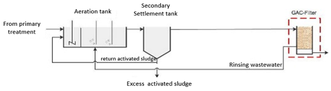
Figure 4: GAC filter following biological treatment
With the second variant, a grain carbon filter is installed to suceed the first filter (see Figure 5). The upstream filter retains the substances that can be filtered after secondary sedimentation, resulting in the grain carbon filter being loaded with virtually solids-free wastewater. This way, the frequency and the type of backwash are reduced.
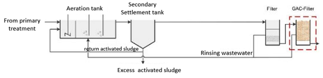
Figure 5: Arrangement of a GAC filter after a wastewater filter
DWA Landesverband Baden-Württemberg
Rennstraße 8 | 70499 Stuttgart | Phone: 0711 89 66 31-0 | E-Mail: info(at)dwa-bw.de
© Deutsche Vereinigung für Wasserwirtschaft, Abwasser und Abfall e. V. // (DWA)
DWA Landesverband
Baden-Württemberg
Rennstraße 8 | 70499 Stuttgart
Phone: 0711 89 66 31-0
E-Mail: info(at)dwa-bw.de
© Deutsche Vereinigung für Wasserwirtschaft, Abwasser und Abfall e. V. // (DWA)